
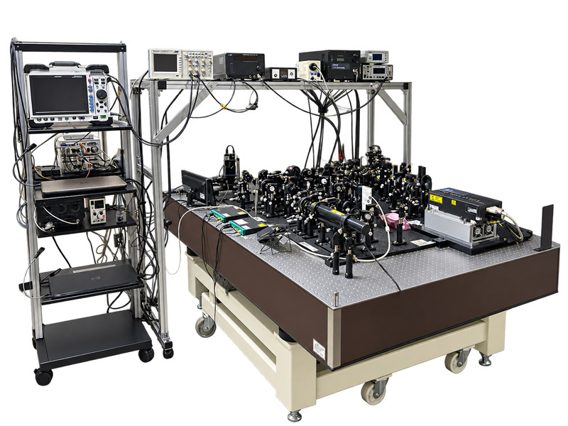
Laser Heterodyne Photothermal Displacement Microscopic Mapping System
|
||||||||||||||||||||||||
|
||||||||||||||||||||||||
|
This microscopic mapping system uses laser heterodyne photothermal displacement (LH-PD) to measure minute thermal expansion displacements at the sample surface and visualize their distribution as a two-dimensional image. The magnitude and temporal response of photothermal displacement, measured without contact or damage to the sample, provide insight into local thermal properties of materials and carrier behavior in semiconductors. By combining microscope optics with an automated XY stage, the system measures photothermal displacement at different positions across the sample surface to visualize local differences in response and spatial variations. In semiconductors, it detects heat generated by the non-radiative recombination of photoexcited carriers, a process in which electrons and holes recombine without emitting light. This can help evaluate the distribution of defects and recombination centers. The acquired temporal response waveforms can be used to estimate thermal diffusivity, thermal conductivity, carrier lifetime, and other properties by comparison with separately performed numerical analyses that account for thermal diffusion and carrier generation, diffusion, and recombination. The data can also be combined with separately prepared machine learning models to estimate spatial distributions of material properties across the sample surface. |
||||||||||||||||||||||||
■Features | ||||||||||||||||||||||||
|
||||||||||||||||||||||||
■Measurement Principle: Laser Heterodyne Photothermal Displacement (LH-PD) |
||||||||||||||||||||||||
|
Laser heterodyne photothermal displacement (LH-PD) is a measurement technique that uses a heterodyne interferometer to detect thermal expansion displacement at the sample surface induced by excitation light. The probe laser beam is split into a reference beam and a measurement beam. An acousto-optic frequency shifter (AOFS) introduces a small frequency difference between the two beams. When the measurement beam reflected from the sample surface is combined with the reference beam, a beat signal corresponding to this frequency difference is produced. Surface displacement changes the optical path length of the measurement beam and thus the phase of the beat signal. This phase change is used to determine the absolute surface displacement. Time-resolved measurement records the phase changes over time, capturing the transient rise and fall of surface displacement as the excitation light is switched on and off.
Note: The material properties that can be evaluated and the estimation accuracy depend on the sample, measurement conditions, and analysis model. |
||||||||||||||||||||||||
■Specifications | ||||||||||||||||||||||||
|
||||||||||||||||||||||||
| *Specifications and appearance are subject to change without notice for product improvement. |
